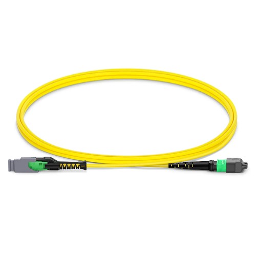
Kenyan network installers should begin with the actual mating interfaces and site fiber records before assigning this product to a link. The 16FMMCMTPSMF jumper supplies a direct transition from a compact MMC-16 APC female connector to an MTP-16 APC Elite female connector. Sixteen OS2 G.657.A1 fibers run through the 2.5mm OFNP cable, allowing newer MMC infrastructure to connect with established MTP-based panels or equipment without adding a cassette between the two interfaces.
Product Highlights
- MMC Female to MTP® Female, 16 Fibers
- OS2 9/125μm, G.657.A1
- MMC insertion loss ≤0.35dB, return loss ≥60dB
- Jumper Polarity wiring scheme
- 2.5mm Plenum (OFNP) cable
- Standard length options: 1m (3ft), 2m (7ft), 3m (10ft)
Specifications
| Part Number | 16FMMCMTPSMF |
|---|---|
| Manufacturer | HT |
| Connector A | US Conec MMC Female (Non-Pinned) |
| Connector B | US Conec MTP® Elite Female (Non-Pinned) |
| Polish Type | APC to APC |
| Glass Fiber | G.657.A1 |
| Fiber Mode | OS2 9/125μm |
| Wavelength | 1310/1550nm |
| Fiber Count | 16 Fibers |
| Polarity | Jumper Polarity |
| Cable Outside Diameter (OD) | 2.5mm |
| Cable Jacket | Plenum (OFNP) |
| Min. Bend Radius (Optical Fiber) | 10mm |
| Min. Bend Radius (Fiber Cable) | 20/10D (Dynamic/Static) |
| Tensile Strength (Long Term) | 30N |
| Tensile Strength (Short Term) | 100N |
| Insertion Loss | ≤0.35dB |
| Return Loss | ≥60dB |
| Attenuation at 1310nm | ≤0.35dB/km |
| Attenuation at 1550nm | ≤0.21dB/km |
| Operating Temperature | -10 to 60°C (14 to 140℉) |
| Storage Temperature | -10 to 70°C (14 to 158℉) |
Using the MMC-to-MTP transition
This cord is valuable when one side of a path has adopted VSFF MMC connectivity and the other remains MTP-16. It reduces the number of intermediate components, but it will not change the optical connector gender: both connector ends are female and non-pinned. Check that the mating MMC and MTP interfaces supply guide pins and that both sides use APC polish before deployment.
One jumper, two connector form factors
Although the optical fiber count is the matching at both connector ends, the MMC and MTP housings have dissimilar physical dimensions and keying features. Technical staff should define each end before routing so the appropriate connector reaches the appropriate panel. Factory jumper polarity defines the optical fiber map across the cable assembly; any further trunk or adapter must retain the intended transmit-to-receive channels.
Length selection and single-mode verification
The standard range is 1m (3ft), 2m (7ft) and 3m (10ft), with project-specific lengths in feet or meters. Insertion loss is limited to 0.35dB and return loss is at least 60dB. Production testing must be complemented by incoming end-face inspection, since dust on either the MMC or MTP ferrule can compromise an otherwise correctly manufactured transition cord.
Ordering and Factory Support
Reference 16FMMCMTPSMF and identify the specified length and number of units. For mixed MMC/MTP channels, list the connected equipment and panel connector genders in your request so the factory can flag any interface mismatch before the leads are built. Project support for Kenya and East Africa is available to reconcile the ordered configuration with the intended installation.