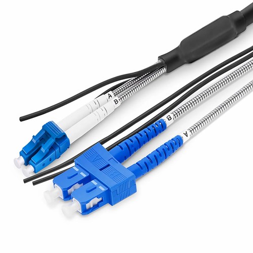
Kenyan network installers should begin with the actual mating interfaces and site fiber records before assigning this product to a link. The project-specific duplex FTTA program builds the standard outdoor base station jumper to the specific arrangement of the site: LC or SC connectors in any mix, the measured pathway length from a few meters to full tower runs, and armored breakout lengths matched to the hardware at each end. The optical cable platform is unchanged: two OS2 9/125µm single-mode fibers of Corning G.657.A1 glass in a 7.0mm LSZH outdoor jacket, with helical steel armored branches protecting the tails and a potted, strain-relieved breakout point.
Product Highlights
- LC, SC and mixed LC/SC combinations on one platform
- Corning G.657.A1 bend-insensitive fiber, 20/10D bend radius
- Armored breakout length selectable: 0.03/0.34/0.2m
- 7.0mm LSZH UV-stabilized outdoor jacket
- Any project length manufactured to order
- Duplex OS2 9/125µm single mode, connector mix to order
Specifications
| Connector Type | LC/SC, mix to order |
|---|---|
| Polish Type | UPC |
| Fiber Mode | OS2 9/125µm |
| Wavelength | 1310/1550nm |
| Fiber Count | Duplex / 2 Fibers |
| Fiber Grade | Corning G.657.A1 |
| Min. Bend Radius (Fiber Cable) | 20/10D (Dynamic/Static) |
| Attenuation at 1310nm | ≤0.36dB/km |
| Attenuation at 1550nm | ≤0.22dB/km |
| Cable Jacket | Low Smoke Zero Halogen (LSZH) |
| Cable Diameter (Outer/Inner) | 7.0/2.0mm |
| Armored Breakout Length (End A/B) | 0.03/0.34/0.2m, selectable |
| Tensile Strength | 200/400N (Long/Short Term) |
| Crush Resistance | 1100/2200N (Long/Short Term) |
| Insertion Loss | ≤0.3dB |
| Return Loss | ≥50dB |
| Operating Temperature | -20 to 70°C (-4 to 158°F) |
| Storage Temperature | -40 to 80°C (-40 to 176°F) |
Configured around the site, not the catalog
Base station sites differ in every dimension: tower height, shelter slot, enclosure type and equipment generation. A project-specific FTTA jumper takes those dimensions as input. The optical connector mix follows the actual ports on the baseband and radio sides, the length follows the measured pathway with working slack, and the armored breakout at each end follows the slot where the trunk cable separates into legs. The result installs without adaptors, without a service loop of surplus cable, and without field termination.
Selecting the armored breakout length
The breakout is the point where the 7.0mm trunk divides into two protected legs. A short 0.03m breakout suits a compact enclosure where both connectors sit side by side; the standard 0.34m armored branch reaches separated ports inside a radio shroud or distribution box; a 0.2m intermediate version covers layouts in between. Specifying the right breakout keeps every centimeter of exposed fiber inside the helical steel tube, which is where crush and rodent damage actually happen.
The same outdoor rating as the standard family
Customization changes the arrangement, not the engineering. The optical cable retains the 200/400N long and short-term tensile rating for pulling and vertical hanging, the 1100/2200N crush resistance, and the -20 to 70 degree Celsius operating range. G.657.A1 glass keeps the 10D static bend tolerance that congested enclosures demand, and remains compatible with deployed G.652.D feeder plant.
Documentation and repeatability for rollouts
For multi-site deployments, the arrangement is recorded once and repeated exactly: connector mix, length, breakout, marking. Crews at site fifty install the identical cord that was validated at site one, which keeps commissioning time predictable and spares planning simple. The marking scheme can adhere to the customer document, with leg identification at both connector ends printed to match the site record.
Standard lengths and custom builds
State the measured pathway length with the request, including the tray channel and working slack at both connector ends; the factory builds to that figure and confirms the manufacturable specification before manufacturing.
Factory testing and quality checks
Every project-specific cord is terminated with precision zirconia ferrule connectors and optically tested as a full product: insertion loss is verified against the 0.3dB ceiling and return loss against the 50dB minimum on each branch leg. End-face geometry is inspected on every connector, and the delivered cord is ready to plug into service without on-site rework.
How to Order and Factory Support
Send the specified connector mix, pathway length and breakout preference with the request. The factory confirms the manufacturable specification before manufacturing and keeps the arrangement on record for repeat orders across the rollout. Project support for Kenya and East Africa is available to reconcile the ordered configuration with the intended installation.