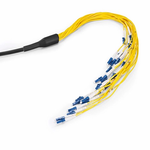
Kenyan network installers should begin with the actual mating interfaces and site fiber records before assigning this product to a link. This project-specific multi-fiber cable is a pre-terminated indoor/outdoor rated product built exactly to the arrangement the project specifies: connector styles and polish at each end, fiber count, jacket rating, breakout geometry and length are all specified at order time, and the finished trunk is optically tested leg by leg before dispatch. Because the indoor/outdoor structure carries a flame-rated jacket that further tolerates moisture and ultraviolet exposure, one product can run from an outdoor entry point directly into the building without a transition splice at the wall.
Product Highlights
- Available from 1-24 Fibers with Variable Length
- Custom Cable with Pre-terminated Connectors, Breakout Types and Pulling Eye
- Optical Performance Test for Normal Network Connections
- Meet the IEC 60794-1 and IEC 60794-2-20 Standard
- Feature a UV Stabilized and Moisture Resistant Outer Jacket
Specifications
| Connector Type | LC/SC/ST/FC/Unterminated |
|---|---|
| Polish Type | UPC/APC |
| Fiber Mode | OS2 9/125μm |
| Fiber Count | 2 Fibers |
| Minimum Bend Radius | 20/10D (Dynamic/Static) |
| Breakout Outside Diameter (OD) | 2.0mm |
| Trunk Outside Diameter (OD) | 5.0mm |
| Insertion Loss | ≤0.3dB |
| Return Loss | UPC≥50dB, APC≥60dB |
| Cable Type | Tight Buffered |
| Fiber Grade | G.657.A1 |
| Operating Temperature | -20 to 60°C (-4 to 140°F) |
Connector and polish discipline on single-mode links
Single-mode plants are unforgiving about polish mismatches: a UPC leg mated into an APC port destroys the return loss and can damage both ferrules. Because this cable assembly is built with the polish specified at order time and tested as a full trunk, the patch side matches the adapter panel side exactly. When documentation is unclear, the boot color tells the truth: green for APC, blue for UPC.
Bend-insensitive glass in real pathways
Backbone routes turn through tight tray corners, congested risers and crowded vertical channels. Because the G.657.A1 bend-insensitive fiber in this cable assembly tolerates a 10mm fiber bend radius, a hurried routing decision during a night upkeep window will not turn into a measurable penalty on the channel. The glass remains fully compatible with the G.652.D plant it connects to.
Breakout geometry and why it matters
The breakout is where a trunk becomes usable. Equal-length legs suit a straight row of adjacent ports, whereas staggered legs reach a column of ports without slack piling up at one end. The 2.0mm legs survive patching-field handling; the 0.9mm model suits protected routing inside panels and cassettes. Specifying the geometry at order time means the cable assembly arrives matching the hardware it serves.
Pulling eye and installation practice
A pre-terminated trunk is only as good as its journey through the pathway. The optional pulling eye protects the connectorized end during the pull and keeps the trunk cable from twisting, which matters on long riser runs and congested trays. The installation load rating on the datasheet is the number the pulling rope should respect, not the weight of the reel.
Pre-terminated versus field termination
Terminating OS2 fiber in the field means a splicer, a tray slot, consumables and the craft time to do it well - multiplied by every fiber in the trunk cable. A pre-terminated product moves all of that work to the factory floor, where polishing, inspection and testing happen under controlled conditions. The installer who receives the optical cable routes it, dresses the legs and mates the optical connectors; the channel is ready for light the matching hour. Since every field-terminated leg is one more chance for a rework visit, for multi-fiber counts the saving is never linear but compounding,.
Planning a trunk route
A multi-fiber trunk is planned once and deployed once; therefore, the planning deserves the hour it takes. Measure the pathway through the actual containment, note the bend space at both connector ends, and decide which end gets pulled. State the pulling eye specification with the order if the pathway is long or congested. At the far end, leave the dressing slack the adapter panel or cassette needs - the datasheet breakout lengths are the default, and other geometries are confirmed before manufacturing.
Selecting the Fiber Count
Fiber count is specified at order time: 1 Fiber, 2 Fibers, 4 Fibers, 6 Fibers, 8 Fibers, 12 Fibers, 24 Fibers are standard options for this structure. Specifying the count is a capacity decision - plan the active links, add the spares the upkeep practice calls for, and the trunk cable arrives with every leg terminated and tested.
Made-to-Order Lengths
Regular lengths cover the common routes: 1m (3ft), 2m (7ft), 3m (10ft), 5m (16ft), 10m (33ft), 15m (49ft), 20m (66ft), 30m (98ft), 25m (82ft), with project-specific length obtainable beyond the list, including foot-based builds for projects specified in imperial units. Specifying the measured pathway length keeps the slack out of the tray and the strain off the optical connectors.
Factory Testing and Quality Checks
Every trunk is terminated with precision zirconia ferrule connectors and optically tested leg by leg before packing: insertion loss and return loss are verified on each fiber, and end-face geometry is inspected for consistent physical contact. The cable assembly ships with dust caps on every connector and the test results obtainable on ask for.
How to Order and Factory Support
Refer to this arrangement by fiber mode, fiber count, connector pair, breakout geometry and length when asking for a quotation. For configurations outside the listed options - mixed connector families, jacket ratings, pulling eye, marking or project packaging - send the specification with the request and the factory will check the build before manufacturing. Project support for Kenya and East Africa is available to reconcile the ordered configuration with the intended installation.