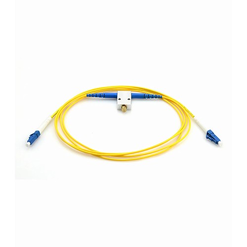
Kenyan network installers should begin with the actual mating interfaces and site fiber records before assigning this product to a link. LC/SC/FC/ST Variable Fiber Optic VOA In-Line Attenuator puts an adjustable attenuation element between two fiber connectors: a calibrated mechanism varies the loss across its range; therefore, one instrument covers the ratings that would otherwise need a drawer full of fixed attenuators. It is the standard tool for receiver sensitivity testing, channel margin verification and power leveling during commissioning.
Product Highlights
- 1310-1550nm(SM)/850-1300nm(MM) Wavelength is free to choose
- Standard Variable Attenuation Values of 0dB up to 60dB
- Applied for CWDM, DWDM, Test Equipment, CATV Systems, Point to Point Systems, etc.
- Attenuating Material-ion Doped Fiber
- Available in a Variety of Connector Types
Specifications
| Attenuation | 0~60dB |
|---|---|
| Operating Wavelength(nm) | 1310~1550(SM)/850~1300(MM) |
| Storage Temperature Range | -40 to 85°C (-40 to 185°F) |
| Operating Temperature Range | -25 to 70°C (-13 to 158°F) |
| Application(1) | Matching Product(1) |
Why links need attenuation at all
Optical links are engineered with a power budget: the transmitter launches, the fiber and connectors consume, and the receiver expects what remains inside a defined window. Short routes, dense wavelength plans and high-power transmitters can all deliver too much light, and an overloaded receiver distorts exactly like an overloaded amplifier - errors appear on a channel that tests perfectly on loss alone. A fixed attenuator brings the received power back inside the window, and the channel behaves as designed.
Ion-doped fiber as the attenuating element
The cleanest way to attenuate light is to absorb it inside the fiber itself. Ion-doped fiber attenuators do exactly that: a short section of doped glass absorbs a calibrated fraction of the optical power and converts it to negligible heat. Because the attenuation happens inside the core, the light that emerges keeps its mode profile and the device adds virtually no reflectance. The alternatives - air gaps, offsets and misaligned ferrules - all trade loss against reflections and modal noise, which is why precision attenuators abandoned them. Kenyan installers can add this check to the handover record for future maintenance and fault tracing.
Variable attenuators at the test bench
The variable optical attenuator is the receiver-test instrument: start at minimum loss, increase attenuation in calibrated steps, and record the point where the channel errors. That sweep defines the receiver sensitivity, the margin of the deployed channel, and the headroom left for aging and repairs. A mechanical VOA covers its range with a stable, reproducible mechanism and reads out on a calibrated scale - no power supply, no software, no drift between visits.
In-line VOA construction for field use
The in-line variable attenuator packages the adjustable element in a cable product with standard connectors; therefore, it inserts directly into the channel under test. Single-mode and multimode versions share the matching operating principle, and the adjustment holds its setting when the instrument moves to the next slot. For commissioning crews who test channel after channel, one in-line VOA replaces a case of fixed attenuators and a bag of adapters.
Handling and cleaning attenuators
An attenuator is a connector with optics inside, and connector rules apply: keep the caps on until the moment of mating, clean every end face before insertion, and never mate a contaminated ferrule into the device - the dirt transfers to the attenuator end face and the next connector that touches it. Store spare units capped and bagged, and record which channel each deployed unit serves so replacement orders match the original rating.
Selecting the right attenuator
Four decisions define the order: the attenuation rating must match the channel calculation, the optical connector range must match the port or the leads, the polish grade must match the plant, and the body style - plug or inline - must suit the installation. Fixed ratings cover permanent installations; the variable instruments cover testing; the test cable covers transceiver qualification. Getting all four right at order time is what turns a small component into a dependable part of the channel.
Factory Testing and Quality Checks
Every attenuator is optically verified before packing: the attenuation rating is measured at the operating wavelengths and checked against its rated tolerance, return loss is verified to its polish grade, and the optical connector end faces are inspected for scratches and contamination. Units ship capped and bagged.
How to Order and Factory Support
Refer to this attenuator by attenuation rating, connector range, polish grade and body style when asking for a quotation. For ratings or configurations outside the listed options - non-standard dB figures, mixed connector pairings or project packaging - send the specification with the request and the factory will check the manufacturable specification. Project support for Kenya and East Africa is available to reconcile the ordered configuration with the intended installation.