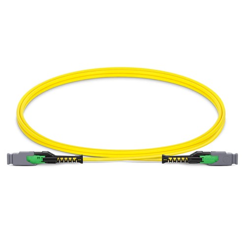
Kenyan network installers should begin with the actual mating interfaces and site fiber records before assigning this product to a link. The 16FMMCSMF jumper links two MMC-16 APC female interfaces with sixteen OS2 fibers in a single 2.5mm plenum cable. It is suited to dense single-mode patching where a compact connector footprint and controlled fiber assignment matter as much as optical loss. G.657.A1 glass supports routing through crowded managers without abandoning single-mode bend performance.
Product Highlights
- MMC Female to MMC Female, 16 Fibers
- OS2 9/125μm, G.657.A1
- MMC insertion loss ≤0.35dB, return loss ≥60dB
- Jumper Polarity wiring scheme
- 2.5mm Plenum (OFNP) cable
- Standard length options: 1m (3ft), 2m (7ft), 3m (10ft)
Specifications
| Part Number | 16FMMCSMF |
|---|---|
| Manufacturer | HT |
| Connector A | US Conec MMC Female (Non-Pinned) |
| Connector B | US Conec MMC Female (Non-Pinned) |
| Polish Type | APC to APC |
| Glass Fiber | G.657.A1 |
| Fiber Mode | OS2 9/125μm |
| Wavelength | 1310/1550nm |
| Fiber Count | 16 Fibers |
| Polarity | Jumper Polarity |
| Cable Outside Diameter (OD) | 2.5mm |
| Cable Jacket | Plenum (OFNP) |
| Min. Bend Radius (Optical Fiber) | 10mm |
| Min. Bend Radius (Fiber Cable) | 20/10D (Dynamic/Static) |
| Tensile Strength (Long Term) | 30N |
| Tensile Strength (Short Term) | 100N |
| Insertion Loss | ≤0.35dB |
| Return Loss | ≥60dB |
| Attenuation at 1310nm | ≤0.35dB/km |
| Attenuation at 1550nm | ≤0.21dB/km |
| Operating Temperature | -10 to 60°C (14 to 140℉) |
| Storage Temperature | -10 to 70°C (14 to 158℉) |
Where this MMC-to-MMC jumper fits
Use this cable assembly between MMC adapter positions or other non-pinned MMC link points in a structured cabling path. Because both connector ends are female, the mating interface must supply the corresponding guide pins. It is never a universal replacement for an LC duplex cord: the sixteen fibers remain in one multi-fiber interface at each end, making the jumper cable most valuable in parallel-optics and densely populated panel environments.
Optical budget and routing details
Each MMC link is specified at 0.35dB maximum insertion loss and at least 60dB return loss. Those ratings belong in the path calculation alongside every adapter and trunk in the pathway. The optical cable has a 10mm minimum fiber bend radius and a 20/10D dynamic/static cable bend specification; leave ample space behind the adapter panel to meet those limits rather than forcing the boot into a sharp turn.
Lengths, polarity and incoming inspection
Regular lengths are 1m (3ft), 2m (7ft) and 3m (10ft), with other lengths obtainable in feet or meters. The model uses jumper polarity, which must be checked against the entire link rather than assumed from the optical connector shape alone. Prior to mating, check APC-to-APC compatibility, check both ferrules and check that the adapter panel key orientation matches the optical connector.
Ordering and Factory Support
Use 16FMMCSMF with the specified length and number of units. For a non-standard pathway, list the desired length, marking and packaging information; our personnel can further examine polarity and gender against the patch-panel schedule before manufacturing. Project support for Kenya and East Africa is available to reconcile the ordered configuration with the intended installation.