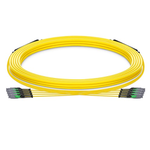
Kenyan network installers should begin with the actual mating interfaces and site fiber records before assigning this product to a link. The project-specific MMC-16 trunk is an OS2 backbone product built around MMC connectors based on sixteen-fiber sub-units. Fiber capacity can scale from 16 to 384 fibers, with cable outside diameter from 4.0 to 17.5mm depending on the specified structure. G.657.A1 glass, APC polish and an OFNP jacket supply the foundation for project-specific single-mode distribution.
Product Highlights
- MMC to MMC, 16-384 Fibers
- OS2 9/125μm, G.657.A1
- MMC insertion loss ≤0.35dB, return loss ≥60dB
- Trunk/ Extender Polarity wiring scheme
- 4.0-17.5mm Plenum (OFNP) cable
- Length and fiber count manufactured to the project requirement
Specifications
| Part Number | XXMMCSMF |
|---|---|
| Manufacturer | HT |
| Connector A | US Conec MMC |
| Connector B | US Conec MMC |
| Polish Type | APC to APC |
| Glass Fiber | G.657.A1 |
| Fiber Mode | OS2 9/125μm |
| Wavelength | 1310/1550nm |
| Fiber Count | 16-384 Fibers |
| Polarity | Trunk/ Extender Polarity |
| Cable Outside Diameter (OD) | 4.0-17.5mm |
| Cable Jacket | Plenum (OFNP) |
| Min. Bend Radius (Optical Fiber) | 10mm |
| Min. Bend Radius (Fiber Cable) | 20/10D (Dynamic/Static) |
| Tensile Strength (Long Term) | 200-400N |
| Tensile Strength (Short Term) | 660-1320N |
| Insertion Loss | ≤0.35dB |
| Return Loss | ≥60dB |
| Attenuation at 1310nm | ≤0.35dB/km |
| Attenuation at 1550nm | ≤0.21dB/km |
| Operating Temperature | -10 to 60°C (14 to 140℉) |
| Storage Temperature | -10 to 70°C (14 to 158℉) |
Engineering the fiber count and cable structure
A trunk is never just a longer jumper. As fiber count increases, sub-unit arrangement, cable diameter, pulling strength and breakout protection become part of the design. This MMC-16 range supports trunk or extender polarity and 200–400N long-term tensile ratings, with 660–1320N short-term ratings across the structure range. The specific ratings appropriate to an order must be confirmed on its production plan.
Backbone routes and panel coordination
Typical uses list links between optical distribution frames, equipment rows and densely populated MMC panels. Pre-termination permits multiple fibers to be deployed in one pull and tested before arrival. The patch-panel schedule should define every sub-unit, connector polarity and gender transition so the trunk cable lands correctly. High fiber counts further require ample rear cable management and static bend space.
Specifying a made-to-project trunk
There is no assumed stock length for this project-specific product. Identify the pathway length in feet or meters, full fiber count, MMC connector gender, polarity, breakout lengths, jacket specifications and marking. Pulling eyes or other installation protection can usually be discussed where the pathway requires them. Length, diameter and tensile structure are confirmed collectively rather than specified individually.
Ordering and Factory Support
Use XXMMCSMF as the MMC-16 trunk range reference and attach a fiber layout or plan. A valuable request includes sub-unit assignment, connector gender, polarity, installation conditions, length and fiber count, allowing the factory to use the appropriate engineered product. Project support for Kenya and East Africa is available to reconcile the ordered configuration with the intended installation.