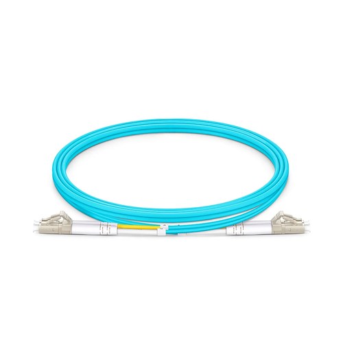
Kenyan network installers should begin with the actual mating interfaces and site fiber records before assigning this product to a link. This OM4 fiber patch cable carries a LC UPC interface on one end and a LC UPC interface on the other, factory terminated on OM4 glass and optically tested as a full product. The duplex zipcord structure keeps the transmit and receive strands paired in one product for fast, error-free patching.
Product Highlights
- Ultra Low Loss Connector with Typical 0.08dB IL
- Bend Insensitive Fiber with 7.5mm Min. Bend Radius
- Precision Zirconia Ferrule Connectors Ensure Low Loss
- Flame-Retardant Riser (OFNR) for Vertical and Floor-to-Floor Installations
- Color-Coded Cable Jacket for Easy Identification
Specifications
| Connector A | LC UPC Duplex |
|---|---|
| Connector B | LC UPC Duplex |
| Fiber Count | 2 Fibers |
| Fiber Mode | OM4 50/125μm |
| Wavelength | 850/1300nm |
| Flame Rating | Riser (OFNR) |
| Cable Outside Diameter (OD) | 2.0mm |
| Polarity | A (Tx) to B (Rx) |
| Cable Type | Tight-Buffered |
| Min. Bend Radius (Optical Fiber) | 7.5mm |
| Min. Bend Radius (Fiber Cable) | 20/10D (Dynamic/Static) |
| Connector Durability | 1000 times |
| Tensile Strength | 90/150N (Long/Short Term) |
| Return Loss | ≥30dB |
| Attenuation at 850nm | ≤3.5dB/km |
| Attenuation at 1300nm | ≤1.5dB/km |
| Operating Temperature | -10 to 70°C (14 to 158℉) |
| Storage Temperature | -20 to 70°C (-4 to 158℉) |
Why OM4 replaced OM3 in new builds
OM4 raises the effective modal bandwidth to 4700 MHz·km at 850nm, and that headroom translates directly into reach for the higher-speed interfaces. Because the price difference against OM3 has largely disappeared, new cabling plants standardize on OM4 and keep OM3 only for matching current installations.
Polarity and pairing in duplex links
A duplex jumper is two fibers with a defined A-to-B crossover. Getting polarity right at the cord level keeps the path consistent end to end, which is why these assemblies are built and tested as a pair rather than as two distinct strands.
Ultra low loss for stretched budgets
Every connector pair spends part of the loss calculation. Ultra low loss terminations cut the per-mated-pair insertion loss to 0.12dB typical, which buys back reach on links that sit at the edge of the specification or frees budget for an extra cassette in the path.
Length Options
Regular lengths cover the common patching routes: 1m (3ft), 2m (7ft), 3m (10ft), 5m (16ft), with project-specific length obtainable beyond the list. Specifying the measured pathway length keeps the slack out of the manager and the strain off the optical connectors.
Quality Control and Testing
Every assembly is terminated with precision zirconia ferrule connectors and optically tested before packing: insertion loss and return loss are verified on each cable, and end-face geometry is inspected for consistent physical contact. The optical cable ships with dust caps on both connectors and the test result obtainable on ask for.
Ordering and Factory Support
Refer to this arrangement by connector pair, fiber mode and length when asking for a quotation. For configurations outside the listed options, mixed connector families, jackets, marking or project packaging, send the specification with the request and the factory will check the build before manufacturing. Project support for Kenya and East Africa is available to reconcile the ordered configuration with the intended installation.