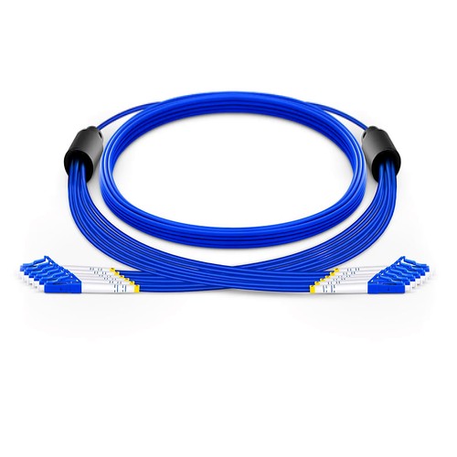
Kenyan network installers should begin with the actual mating interfaces and site fiber records before assigning this product to a link. This configured-to-order product puts six OS2 9/125µm G.657.A1 fibers in a single armored 4.5mm round trunk, breaking out to six individual 3.0mm legs terminated with any mix of LC, SC, FC or ST connectors in UPC or APC polish. One pull replaces three independent duplex leads, and the helical stainless steel armor protects the whole group along routes where independent jumpers would each need protection.
Product Highlights
- Three duplex circuits or six simplex legs per assembly
- LC, SC, FC or ST connectors in any leg mix, UPC or APC
- Riser (OFCR), LSZH or plenum (OFNP) jacket options
- 0.3m or 0.5m breakout legs in 3.0mm armored sub-units
- 200/400N tensile rating for trunk pulls
- 6 fibers OS2 9/125µm in one armored 4.5mm trunk
Specifications
| Connector Type | LC / SC / FC / ST, any leg combination |
|---|---|
| Polish Type | UPC or APC per leg |
| Fiber Mode | OS2 9/125µm |
| Wavelength | 1310/1550nm |
| Fiber Count | 6 Fibers |
| Flame Rating | Riser (OFCR) / LSZH / Plenum (OFNP) |
| Fiber Grade | G.657.A1 (Compatible with G.652.D) |
| Min. Bend Radius | 30D |
| Insertion Loss | ≤0.3dB |
| Return Loss | UPC ≥50dB, APC ≥60dB |
| Attenuation at 1310nm | ≤0.36dB/km |
| Attenuation at 1550nm | ≤0.22dB/km |
| Trunk OD | 4.5mm |
| Breakout OD | 3.0mm |
| Breakout Length | 0.3m / 0.5m |
| Polarity | A (Tx) to B (Rx) |
| Armor Layer | Stainless Steel Tube |
| Tensile Strength | 200/400N (Long/Short Term) |
| Operating Temperature | OFNP: 0 to 70°C; OFCR/LSZH: -20 to 70°C |
| Storage Temperature | -40 to 70°C (-40 to 158°F) |
Six fibers in a single armored round cable
Three duplex links generally mean three independent leads competing for space in the matching tray. This cable assembly consolidates them into one 4.5mm armored trunk with six fibers, which pulls faster, dresses cleaner and presents only one cable to every pathway pinch point. At the far end the trunk cable fans out into individual legs that land exactly where three independent leads would have.
Breakout design and leg options
The breakout point is obtainable with 0.3m or 0.5m legs in 3.0mm armored sub-units, each terminated with LC, SC, FC or ST connectors as the job requires. Legs can usually be mixed, for example LC toward the switch and SC toward the adapter panel, and each branch leg is labeled so the three circuits stay identifiable following installation.
Reducing cable count in congested pathways
Tray fill, sleeve capacity and bend space are the limits that actually stop retrofits. Replacing three leads with one trunk cuts the optical cable count by two thirds on that pathway, and the 200/400N tensile rating lets the single trunk tolerate the pull that three loose leads never would. For riser, LSZH or plenum zones the jacket is matched to the building section.
Labeling and circuit management
With six fibers in one trunk, identification is part of the build, not an afterthought. Legs are labeled at both connector ends, and the marking scheme can adhere to the customer document: circuit numbers, room codes or port references. For phased rollouts the matching scheme repeats on every batch; therefore, a technician picking up the installation in month six reads the leads exactly as the first crew left them.
Trunk construction in detail
Inside the 4.5mm jacket the six tight-buffered fibers are stranded around a central strength member, wrapped in aramid yarn and then in the helical stainless tube, with the outer compound extruded over the armor. That layering is what permits a 200N long-term pull rating in a trunk this thin. The breakout point is potted and strain-relieved so the transition from trunk to legs carries no load into the ferrules.
Standard lengths and custom builds
Trunk lengths adhere to the standard stocked range: 1m (3ft), 2m (7ft), 3m (10ft), 5m (16ft), 10m (33ft), 15m (49ft), 20m (66ft) and 30m (98ft), with other lengths built to order. State the breakout length and leg marking scheme with the request so the breakout point lands correctly at both connector ends.
Factory testing and quality checks
Every leg of every assembly is terminated with precision zirconia ferrules and measured for insertion loss and return loss before packing; the 0.3dB ceiling and polish-proper return figures are verified per fiber, not per batch sample. The breakout point point is strain-relieved and the whole product is pull-tested to its rated load.
How to Order and Factory Support
Send the leg connector mix and polish, the jacket rating, trunk length and breakout length. The factory confirms the arrangement plan with the quotation; marking specifications for the three circuits can usually be added to the matching plan. Project support for Kenya and East Africa is available to reconcile the ordered configuration with the intended installation.